|
Train Trek Layout Simulation™ To Get You Started in 3 Easy Steps... |
|
|
|
|
| Step 1: Serial Port Communication Setup | |
|
Before running your digital layout, you need to setup the communication protocol between Train Trek Layout Simulation™ (LS)™ and the Märklin interface (6051). Train Trek Layout Simulation™ (LS)™ is equipped with an automatic communication setup utility that is already pre-set for Märklin Digital Interface unit (6051). All you need to do is to setup the PORT. |
|
|
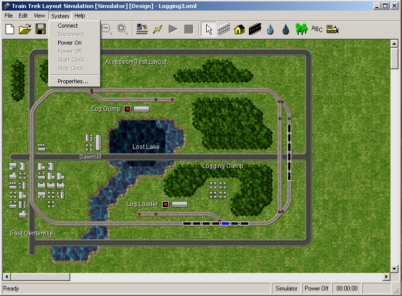
To activate the communication setup utility, simply click on the 'System' pull-down menu and select: 'Properties'.
|
|
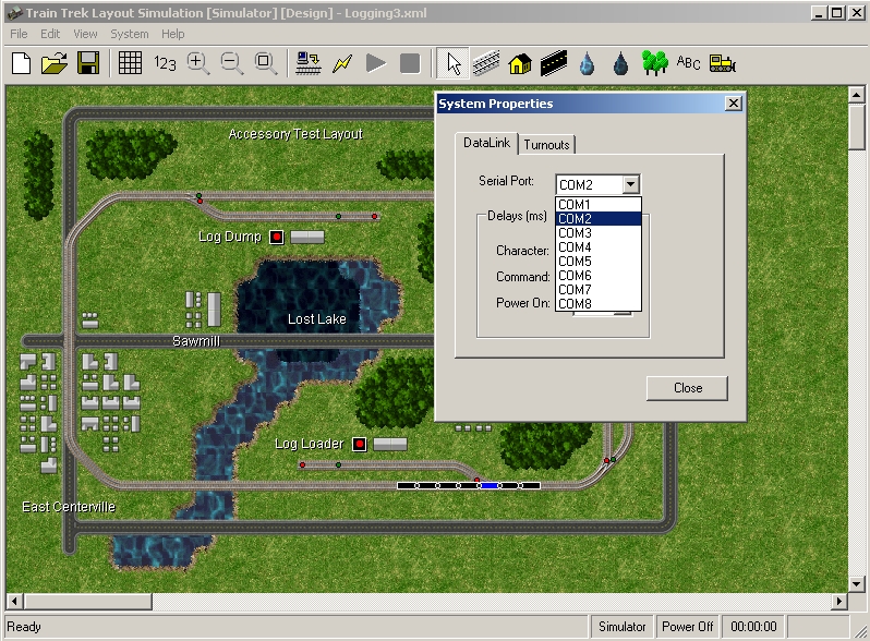
| Communication PORT setup | |
|
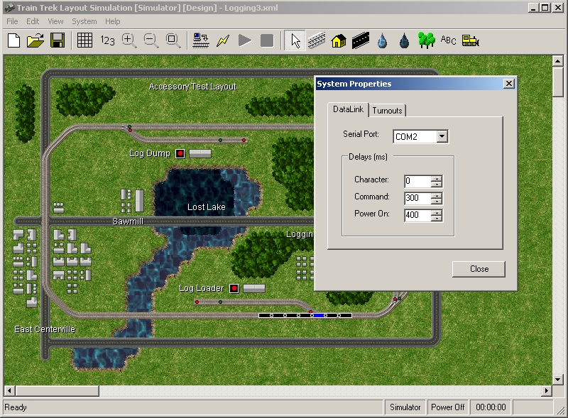
The Communication Auto Setup utility is already pre-set with the Märklin Interface setup (8 data bits, 2400 Baud Rate, 2 Stop bits, No Handshaking). Simply select the PORT that is connected to the Märklin Interface. Typically, your computer will have at least two (2) PORTS. One port is for Modem use. The second PORT is an available communication PORT (9 PIN DB).
it is recommended to leave all other parameters as default since it was tested successfully with Marklin Digital system.
To complete the communication setup simply click on the 'Close' button. That's It! You are ready to test the connection between Train Trek Layout Simulation™ (LS)™ and the Märklin Interface unit (6051). Warning! Without the correct communication setup Train Trek Layout Simulation™ will not be able to control your layout!
|
|
| Stage 2: Testing for 'Active' Communication | |
|
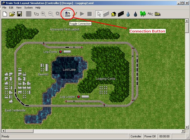
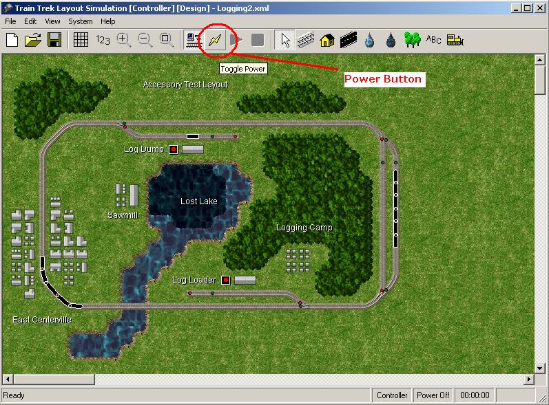
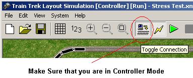
The simplest and quickest way to do so is to turn the system's POWER ON/OFF. In the 'Information Panel', click on the 'Toggle Connection' button (see figure below). This button is aimed to switch between the simulator and the controller. In order to control the trains, you must switch to Controller mode. In this mode only, you can turn the system's power ON/OFF and control digital components.
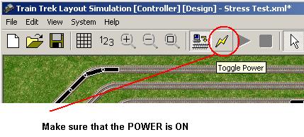
After switching to Controller Mode (Observe the window caption [Controller]), you may click on the Power Button to turn the system's power ON/OFF. Click on the power button few times and observe the Märklin Interface Power Indicator (Red LED Light). It should turn ON when the POWER button is turned ON and OFF when the POWER button is in the OFF position.
Your communication has successfully been established and you are ready to run your layout! If you are NOT able to turn the system's power ON/OFF, re-open the Communication Auto Setup window and change the PORT settings. For example: If your setup was on PORT #1 change it to PORT #2. Then try to turn the system's POWER ON/OFF again. Typically a computer is equipped with at least two (2) communication PORTS. If your computer is equipped with more than two (2) PORTS then try each one of them to establish communication successfully. |
|
| Stage 3: Running Trains and activating turnouts | |
|
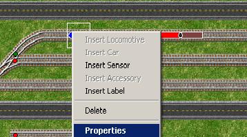
The simplest and quickest way to run your trains is to load our sample layout, place few trains and turnouts on it and run it! A. Load the Sample Layout named: Sample1. (It is located under: Examples folder) B. Please noticed that the sample layout includes one train with the default address: 1. If you have a train with this digital address, then you may simply run it. If you do not have trains with this digital address, right click on the locomotive, select properties and change it's address to the desired digital address!
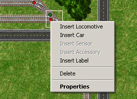
Right click on any locomotive, select Properties to change it's Digital Address. C. For manual Run: 1. Make sure that you are on 'Controller' Mode.
2. Make sure that the system POWER is ON.
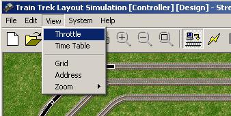
3. Open the Throttle Panel by clicking on the pull-down menu: 'View'. Select: 'Throttle'.
4. Select the desired train's address and slowly slide the speed control slider. Noticed that your train is moving! Remember: The program will NOT control your trains and turnouts in SIMULATION Mode! You have to switch to Controller mode, in order to operate your layout live! D. Turnouts Operation: Notice that the sample layout included 2 turnouts. Their address are 1 and 2 respectively. If you already have turnouts with these digital addresses then you can control them immediately, simply by Double Click on each turnout. If you do not have turnouts with these addresses, right click on any turnouts and select properties to change the turnout Digital address. After changing it's address, you can simply activate it by Double Click on it. One Double Click will change the position once. Another Double Click will change the position twice.
Right click on any turnouts, select Properties to change the turnout Digital address. That's It! |
|
|
If you are able to Manually Control Your System!
Tayden Design Technical Publications |
|